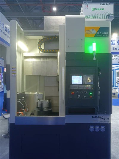
The components of high-speed vertical lathes combine the basic structure of traditional vertical lathes with optimized components of high-speed and intelligent design. They can be specifically divided into the following core components:
1. Bed and base
Made of high-strength cast iron or alloy materials, the base is thermally aged to eliminate internal stress and ensure overall rigidity and vibration resistance. The base is usually integrated with the workbench to support the stable operation of the whole machine.
2. Spindle system
The spindle mostly adopts a short spindle structure, and high-precision centering is achieved through a combination of double-row tapered roller bearings and thrust ball bearings, with strong axial load-bearing capacity. An encoder can be installed on the top of the spindle, and the speed information can be fed back in real time with the coupling, supporting constant linear speed cutting and thread processing. The spindle of some models is linked with the workbench, and the CNC system accurately controls the speed range.
3. Workbench
The horizontally arranged circular workbench, with the spindle driven to rotate vertically, is suitable for clamping large disks, shafts and complex parts. The surface of the workbench usually has a T-slot or fixture interface to meet diverse processing needs.
4. Column and beam
The column is a box-type structure with an integrated guide rail to support the beam and tool holder system. The beam can move vertically along the column guide rail to provide Z-axis feeding function. Both are made of high-strength materials and precision processing technology to ensure dynamic rigidity.
5. Tool holder system
Includes vertical tool holder, side tool holder or multi-station compound tool holder (such as pentagonal tool holder), supporting automatic tool change function. The tool holder is equipped with servo drive to achieve horizontal, vertical and oblique feeding. Some models integrate milling, drilling and other composite processing modules.
6. CNC and drive system
Adopt high-precision CNC system with integrated programming, parameter setting and fault diagnosis functions. The feeding system is driven by servo motor or variable frequency motor to achieve stepless speed change and precise displacement control. The light rod, lead screw and gear box cooperate to complete automatic feeding and thread processing.
7. Guide and transmission mechanism
Use high-precision linear guides or V-shaped/flat guide combinations, combined with ball screws or hydrostatic guide technology to ensure the smooth movement and repeatability of the tool slide.
8. Auxiliary system
Including hydraulic or pneumatic clamping devices, cooling and lubrication systems, and optional tailstocks, workpiece measuring probes, etc., to further improve the level of automation.