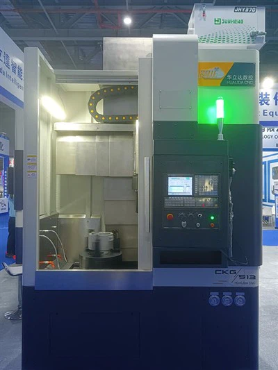
Adjusting the spindle orientation on a CNC vertical turning lathe is a critical process that can significantly impact the precision and efficiency of machining operations. As a supplier of CNC Vertical Turning Lathes, including models like the CKG513 CNC Vertical Lathe, CKG5110 CNC Vertical Turning Lathe, and CKG515 CNC Vertical Lathe, I understand the importance of proper spindle orientation adjustment. In this blog, I will share some insights and steps on how to adjust the spindle orientation on a CNC vertical turning lathe.
Understanding the Importance of Spindle Orientation
The spindle is the heart of a CNC vertical turning lathe. It holds the cutting tool and rotates at high speeds to perform machining operations. The correct spindle orientation ensures that the cutting tool engages with the workpiece accurately, resulting in precise cuts, smooth surface finishes, and dimensional accuracy. Incorrect spindle orientation can lead to a variety of problems, such as poor surface quality, inaccurate dimensions, and premature tool wear.
Pre - adjustment Preparations
Before attempting to adjust the spindle orientation, it is essential to take several preparatory steps:
- Safety First: Ensure that the lathe is powered off and locked out to prevent accidental startup. Wear appropriate personal protective equipment, including safety glasses, gloves, and ear protection.
- Clean the Workspace: Remove any debris, chips, or coolant from the lathe bed, spindle, and surrounding areas. A clean workspace will prevent contaminants from interfering with the adjustment process.
- Inspect the Spindle and Components: Check the spindle for any signs of damage, such as cracks, excessive wear, or loose components. Inspect the bearings, belts, and couplings to ensure they are in good condition.
- Gather the Necessary Tools: You will need a variety of tools for the adjustment process, including precision measuring instruments (such as dial indicators), wrenches, and shims. Make sure all tools are clean, calibrated, and in good working condition.
Step - by - Step Spindle Orientation Adjustment
The following is a general guide to adjusting the spindle orientation on a CNC vertical turning lathe:


- Mount the Dial Indicator: Mount a high - precision dial indicator on the lathe bed or a stable fixture. Position the indicator so that its probe contacts the spindle nose or a reference surface on the spindle.
- Set the Indicator to Zero: Rotate the spindle slowly by hand and adjust the indicator so that it reads zero at a specific point on the spindle's rotation. This will serve as the reference point for the adjustment.
- Check the Radial Runout: Rotate the spindle through a full revolution while observing the dial indicator. The radial runout is the maximum deviation of the spindle from its true center. For most applications, the radial runout should be within the manufacturer's specified tolerance, typically a few thousandths of an inch.
- If the radial runout is outside the tolerance, you may need to adjust the spindle bearings or realign the spindle. Loosen the bearing housing bolts slightly and use shims to make small adjustments to the bearing position. Tighten the bolts gradually and re - check the runout until it is within the acceptable range.
- Check the Axial Runout: In addition to radial runout, you also need to check the axial runout, which is the movement of the spindle along its axis. Mount the dial indicator so that its probe contacts the face of the spindle nose. Rotate the spindle and observe the indicator reading. The axial runout should also be within the specified tolerance.
- To adjust the axial runout, you may need to adjust the thrust bearings or the spindle nut. Loosen the relevant components and make small adjustments using shims or adjusting nuts. Re - check the axial runout after each adjustment.
- Check the Spindle Taper Alignment: If the lathe uses a tapered spindle nose to hold the cutting tools, it is crucial to ensure that the taper is properly aligned. Use a taper gauge or a precision measuring device to check the taper angle and alignment.
- If the taper is misaligned, you may need to clean and re - seat the spindle taper or use shims to correct the alignment. Make sure the taper is clean and free of debris before making any adjustments.
- Fine - Tuning: Once you have made the initial adjustments, re - check the radial runout, axial runout, and taper alignment. Make any necessary fine - tuning adjustments to achieve the optimal spindle orientation. This may involve making very small changes to the shim thickness or component position.
Post - adjustment Checks
After completing the spindle orientation adjustment, perform the following post - adjustment checks:
- Re - check the Runout: Rotate the spindle again and verify that the radial and axial runouts are still within the specified tolerance. Make any final adjustments if necessary.
- Test Run: Power on the lathe and perform a test run at a low speed. Observe the machining operation closely to ensure that the cutting tool engages with the workpiece smoothly and that the surface finish and dimensional accuracy are satisfactory.
- Record the Adjustments: Document the adjustments made during the process, including the shim thicknesses, component positions, and any other relevant information. This record will be useful for future reference and maintenance.
Troubleshooting Common Problems
During the adjustment process, you may encounter some common problems:
- Persistent Runout: If the runout remains outside the tolerance after multiple adjustments, there may be a more serious issue, such as a damaged spindle or worn bearings. In this case, it may be necessary to replace the damaged components.
- Difficulty in Adjustment: If you are having difficulty making the necessary adjustments, it could be due to improper tool selection, incorrect adjustment techniques, or underlying mechanical problems. Consult the lathe's manual or seek the assistance of a qualified technician.
- Vibration: Excessive vibration during the test run may indicate an imbalance in the spindle or a misaligned component. Check the balance of the cutting tool and the spindle, and re - check the alignment of all components.
Conclusion
Adjusting the spindle orientation on a CNC vertical turning lathe is a complex but essential process. By following the steps outlined in this blog, you can ensure that your lathe's spindle is properly oriented, resulting in high - quality machining operations. As a supplier of CKG513 CNC Vertical Lathe, CKG5110 CNC Vertical Turning Lathe, and CKG515 CNC Vertical Lathe, we are committed to providing our customers with the best - in - class products and technical support. If you have any questions or need further assistance with spindle orientation adjustment or any other aspect of our CNC vertical turning lathes, please do not hesitate to contact us for procurement and in - depth discussions.
References
- CNC Vertical Turning Lathe Operation Manuals
- Precision Machining Handbook
- Spindle Manufacturing and Maintenance Guidelines