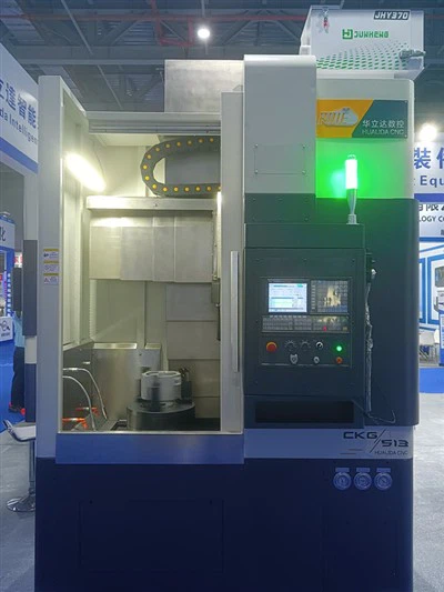
Hey there! As a supplier of CNC turning and milling machines, I know how crucial it is to keep these bad boys calibrated. A well - calibrated CNC turning and milling machine can make all the difference in the quality and precision of your work. So, let's dive right in and talk about how to calibrate a CNC turning and milling machine.
Why Calibration Matters
First off, let's understand why calibration is so important. When you're using a CNC Turning and Milling Machine Tools, you're relying on it to cut, shape, and form materials with extreme precision. If the machine isn't calibrated correctly, you'll end up with parts that are out of spec. This can lead to a whole bunch of problems, like parts not fitting together properly, reduced product quality, and even increased waste. In short, calibration ensures that your machine is performing at its best and that you're getting the most out of your investment.
Pre - Calibration Checks
Before you start the actual calibration process, there are a few pre - checks you should do. First, take a good look at the machine for any signs of damage or wear. Check the belts, pulleys, and screws to make sure they're tightened properly. If you notice any loose parts, tighten them up. A loose screw or a worn - out belt can throw off the calibration big time.
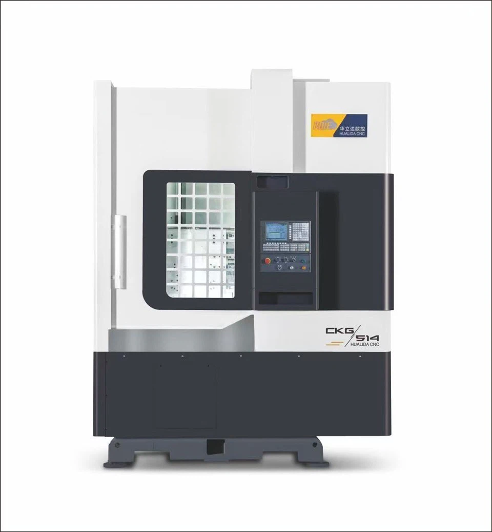

Next, clean the machine thoroughly. Any dirt, debris, or coolant residue can affect the accuracy of the calibration. Use a clean cloth and some appropriate cleaning agents to wipe down all the surfaces, especially the guideways and the spindle.
Axis Calibration
The first major step in calibrating a CNC Lathe and Milling Machine is to calibrate the axes. The axes are the different directions in which the cutting tool can move, usually the X, Y, and Z axes.
Step 1: Measure the Axis Movement
For each axis, you'll need to measure how much it moves in response to a given command. You can use a high - precision linear encoder or a laser interferometer to do this. These tools are incredibly accurate and will give you the exact amount of movement.
First, send a specific command to the axis to move a certain distance, let's say 100 mm. Then, use your measuring tool to check how far the axis actually moved. If there's a difference between the commanded distance and the actual distance, you'll need to adjust the axis calibration parameters.
Step 2: Adjust the Axis Parameters
Most CNC machines have a control panel where you can access the calibration settings. Look for the settings related to the axis you're calibrating. You'll usually find options to adjust the backlash, the pitch error compensation, and the scale factor.
Backlash is the small amount of play or movement in the axis when the direction of movement is reversed. To adjust the backlash, you'll need to measure it first using your measuring tool. Then, enter the measured value into the control panel to compensate for it.
Pitch error compensation is used to correct any errors in the pitch of the lead screw or ball screw that drives the axis. If the screw has a slight variation in its pitch, it can cause the axis to move inaccurately. The control panel will allow you to enter a compensation curve based on the measured pitch errors.
The scale factor is used to adjust the overall movement of the axis. If the axis is moving too much or too little compared to the commanded distance, you can adjust the scale factor to correct it.
Spindle Calibration
The spindle is another critical component of a CNC Turning and Milling machine. It holds the cutting tool and rotates at high speeds to perform the cutting operations.
Step 1: Check the Spindle Speed
Use a tachometer to measure the actual spindle speed. Compare it with the speed set on the control panel. If there's a difference, you may need to adjust the spindle drive parameters. Most modern CNC machines use a variable - frequency drive (VFD) to control the spindle speed. You can usually access the VFD settings through the machine's control panel and make adjustments to the frequency and voltage to achieve the correct speed.
Step 2: Inspect the Spindle Runout
Spindle runout refers to the amount of wobbling or deviation from the perfect rotational axis. Excessive runout can cause poor surface finish on the machined parts and can even damage the cutting tools. To check the spindle runout, you can use a dial indicator. Mount the dial indicator on the machine's table and position the probe against the spindle nose. Rotate the spindle slowly and observe the reading on the dial indicator. If the runout exceeds the recommended tolerance, you may need to check the spindle bearings or the alignment of the spindle. In some cases, you may need to replace a worn - out bearing to correct the runout.
Tool Offset Calibration
Tool offset calibration is essential for ensuring that the cutting tools are positioned correctly relative to the workpiece. Each cutting tool has its own length and diameter, and these dimensions need to be accurately measured and entered into the CNC control system.
Step 1: Measure the Tool Length
You can use a tool presetter to measure the length of the cutting tool accurately. A tool presetter is a device that allows you to measure the tool's length and diameter outside of the machine. Once you've measured the tool length, enter the value into the CNC control system's tool offset table.
Step 2: Measure the Tool Diameter
Similarly, measure the diameter of the cutting tool using the tool presetter. Enter the measured diameter value into the tool offset table as well. The CNC control system will use these values to compensate for the tool's dimensions and ensure that the cutting operations are performed at the correct position.
Post - Calibration Checks
After you've completed all the calibration steps, it's important to do some post - calibration checks. Run a test program on the machine to machine a sample part. Use precision measuring tools like calipers, micrometers, or a coordinate measuring machine (CMM) to check the dimensions of the sample part. Compare the measured dimensions with the design specifications. If the dimensions are within the tolerance range, then your calibration was successful. If not, you may need to go back and re - check some of the calibration settings.
Conclusion
Calibrating a CNC turning and milling machine may seem like a daunting task, but with the right tools and a systematic approach, it's definitely doable. Remember, regular calibration is key to keeping your machine running smoothly and producing high - quality parts.
If you're in the market for a new CNC turning and milling machine or need more guidance on calibration, don't hesitate to reach out. We're here to help you make the best choices for your manufacturing needs. Contact us and let's start a conversation about how we can assist you in getting the most from your CNC machines.
References
- "CNC Machine Tool Calibration Handbook"
- "Precision Manufacturing and Machine Technology" textbook